

Earthquakes are one of the most dangerous and destructive forms of natural hazards.
They strike with sudden impact and no warning. They may occur at any time of day or on
any day of the year. An earthquake can devastate an entire city or a region of hundreds of
square kilometres. In the past 3 centuries over 3 million people have died due to
earthquakes and earthquake related disasters. The economic losses estimated for the
period 1929-1950 are in excess of US$10 billion.

About 2/3 of the earths crust is seismically active, which means that about 1,000,000,000
people are living in areas of the world that are prone to earthquakes. Earthquakes cannot
be prevented nor accurately predicted and when earthquakes occur near densely
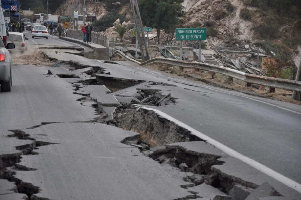
populated areas, grave consequences can be expected. In most cases it is not the ground
shaking itself that causes life and economic loss but the collapse or damage of buildings
and infrastructure that are too “weak” to resist the ground shaking.
It is obvious that thecollapse of a building can directly cause deaths and economic losses however, even slight damage to industrial facilities or manufacturing machinery can cause an interruption of business and consequent economic loss.
Furthermore, if there is an extended closure of facilities, indirect economic losses may be incurred from the loss of market share.
Damage to infrastructure, such as roads and railways, can impede the disaster relief and
rescue efforts. Damage to schools, hospitals and health care facilities can also have
severe consequences on life loss and health care after the event. It is a known fact that
economic losses due to the event and the bad management of rescue and relief operations
have lead to political upheavals in the past.
So what can we do as engineers?
….. Simple, design structures to withstand ground motion with the aim or reducing the
possible life and economic losses that may happen if an earthquake occurs.
An earthquake usually constitutes the most severe loading to which most civil engineering structures might possibly be subjected (note: lateral loads imposed by winds = 1-3% of building weight whereas those due to earthquakes = 25-30% of building weight). And yet in most parts of the world, even those that are highly seismic, there is a possibility that an earthquake may not occur during the life of the structure.
It is generally uneconomic, and often unnecessary to design structures to respond to design-level earthquakes in the elastic range (i.e. for the same levels of internal strains that you would design a structure for considering gravity loads). If the strength of the structure’s lateral force resisting system is developed at a level of seismic response less than that corresponding to the design earthquake, inelastic deformations may result, involving yielding of steel and possibly concrete or masonry crushing. Provided that the strength does not degrade as a result of the inelastic action, acceptable response can be obtained. Displacements and damage must however, be controlled at acceptable levels.
Seismic design uses concepts of controlled damage and inelastic energy absorption!
Indeed buildings are generally designed for only about 10-30% of the elastic earthquake lateral loads, but a lateral resisting system and structural detailing are chosen and designed to allow the structure to undergo inelastic deformations without losing strength. In this manner the energy imparted by the earthquake is dissipated through the inelastic deformation and controlled damage.
Limit States
As in the case of design codes for gravity loads, in earthquake engineering a framework of limit states (or performance levels) are used to design and check the building. Most codes of practice design to a single limit state (ultimate) but carry out checks to satisfy other limit states (e.g. serviceability). Conceptually the limit states for seismic design are:
1. Serviceability: the function of the structure is not disrupted. Cracking of concrete and limited yield of steel is allowed provided that the need for repair does not arise.
2. Damage Control: repairable damage is inflicted on the structure in the form of wide cracks in concrete and cover spalling, and small permanent deformations in steel members.
3. Life-safety: heavy irrepairable damage may occur but collapse and loss of life are avoided.
These limit states can have different names in different seismic codes. Current model codes such as UBC and IBC have two main purposes:
• Provide minimum provisions for the design and construction of structures to resist earthquake effects.
•“…to safeguard against major structural failures and loss of life, not to limit damage or maintain function” (UBC, 1997 ed., Section 1626)
Capacity Design
The capacity design approach explicitly considers the problem of determining the failure mechanism of members. The basic idea is to force the member to fail in a ductile manner by making the capacity of the member in other possible failure modes greater. It involves the simple application of plastic analysis on an element-wise basis as shown below.
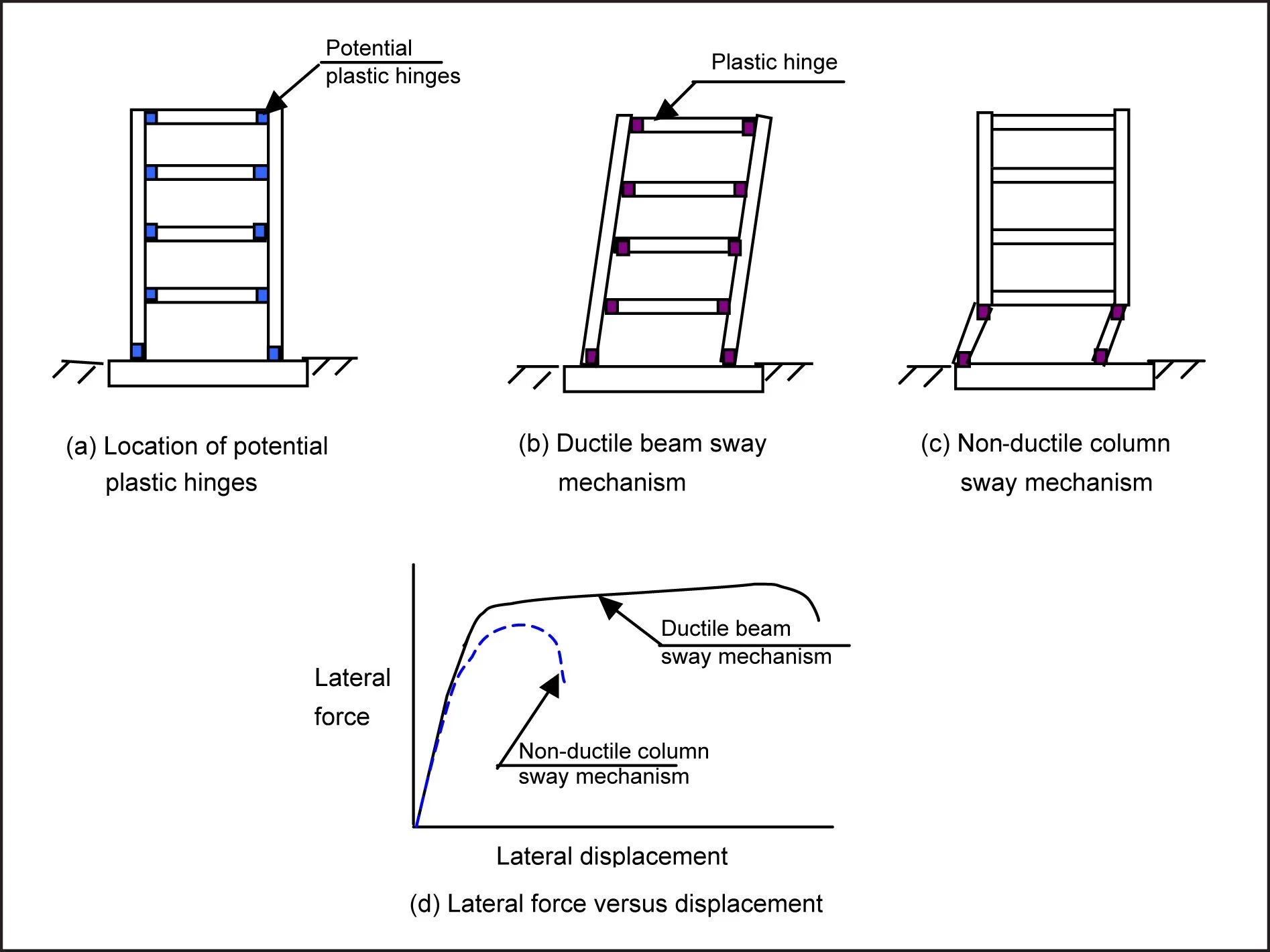
Figure 1 :Failure mechanism for (b) strong-column - weak beam structure and (c) weak column-strong bream structure.
In seismic design the member and structure over-strength is very important. For example, if you under-estimate the strength of structural members in gravity load design it is safe and conservative, however, in the case of seismic design this can be very dangerous. This is because the location and the sequence of formation of member capacity (and therefore the progression of damage in the structure) are important for collapse prevention. This is shown in Figure 1, which shows two buildings. The first has formed plastic hinges in its beams and is undergoing spread displacement, with uniform distribution of damage (hinges) up the structure height. The second structure has instead formed plastic hinges in the top and bottom of the columns of one floor. This structure shows concentrated damage (and displacement) in one storey. It is clearly unstable and prone to catastrophic collapse through “soft-storey” failure. This type of failure is commonly seen in cases where the capacity of the beams has been under-estimated and the hinges have formed in the weaker columns first (strong-beam, weak-column failure).
Summing up
Central to the safety of the structure and to the assumption that you have a good structural ductility (and therefore can reduce the seismic loads) is to avoid failure in brittle modes (such as shear failures and failure in areas that would cause structural instability such as columns). To ensure that failure occurs in the desired mode and that damage occurs only at the desired locations, the concept of “capacity design” is used. We have briefly touched upon the concept of Capacity Design when speaking of the different failure modes illustrated in Figure 1.
Capacity design states that “critical sections are not designed to the applied action effects, but to the values of action effects consistent with the strength of the protected zones, taking into account all possible sources of overstrength”.
For example in a moment resisting frame, the beams are designed first for the earthquake, dead and live load action combinations. The moment capacity and shear capacity of the beam are then determined from the section design. These capacities are factored up to account for sources of overstrength such as an unintentional increase in the yield strength
of the steel or from rounding off the area of reinforcement. Finally the columns are designed to resist the factored beam moment and shear capacities, (i.e. the columns are not designed to solely resist the applied loads, but are designed to be stronger than the beams so that the beams will always yield first!!).